|

|
|
|
System
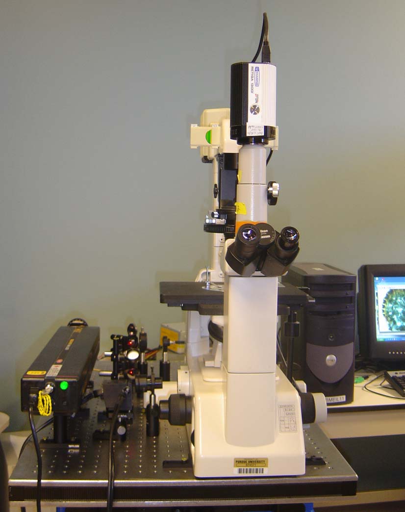
Fig. 1 CSLM system setup: (a) schematic diagram; (b) system photo. L: laser; M: reflection mirror; BS: beam splitter; G: galvanometer; PO: polarizator; FC: fiber collimator; OF: optical fiber; D: detector. A stationary reflection measurement was processed with a mirrored slide to evaluate the axial dissection capability of our system [5]. The Nikon 40x NA 1.30 oil-immersion objective was used. From Fig. 2 we can see that , the FWHM was measured to be 1.1 μm in our system. The measurement was repeated on MRC-1024 with the iris be 1.0 mm and the results was 0.9 μm. It should be noted that, the stationary reflection is not directly related with the axial resolution but it provides a comparable parameter that can be easily used for system evaluation.
Fig. 2 Measurement of axial resolution with the mirrored slide reflection.
|
|
|