|

|
|
|
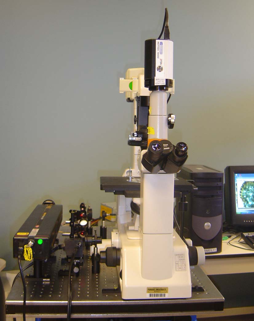
The laser we used was a He-Ne laser with 633nm emission. The laser beam was guided onto a pair of galvanometers (6215H , Cambridge Technologies) for horizontal (fast axis) and vertical (slow axis) scanning. The controlling units for the two galvanometric axes were also commercially provided for the best performance of the galvanometers. A DC power supply was used to supply voltage for the controlling unit. A Nikon Diaphot 200 inverted microscope was used as the prototyping tool for the setup of our CSLM. Conix Z-axis motor (CZM, Conix Research) was employed to control the focal depth in the sample with a precision of 0.1μm. We used Nikon CFWN 10x eyepiece to construct the scanning plane at the side-view port of the Nikon Diaphot 200. The laser was focused onto the sample through a microscopic objective.
(a) (b) Fig. 1 CSLM system setup: (a) schematic diagram; (b) system photo. L: laser; M: reflection mirror; BS: beam splitter; G: galvanometer; PO: polarizator; FC: fiber collimator; OF: optical fiber; D: detector.
The signal from the sample goes back to the galvanometers and is de-scanned. Thus, the return signal exactly follows the path of incidence. A beam splitter is used to reflect the return signal. A fiber collimator (FC220FC-A, Thorlabs) is used to focus the backscattered signal, and a 9 μm core-size optical fiber (S1-F2 F2-01-0020-GF, Go4Fiber) conducts the signal into a PMT detector (HC120-13 MOD, Hamamatsu). The fiber also acts as the pinhole for confocal detection. A polarizer placed between the beam splitter and the fiber collimator blocks the specular reflection. The driving signal for the galvanometers is provided with National Instruments PCI 6251 Data Acquisition System. It is also used as the A/D converter for the photodetector, to digitize the analog signal to 8-bit digital signal for imaging. The signal driving and data collection program is programmed and compiled with National Instruments LabView 7. The program generates a 512Hz step saw-tooth signal for the horizontal scanning, and a 2Hz step saw-tooth signal for the vertical scanning. As both the forward and backward scanning are used, the frame speed is 256 ×256 at 4 frames per second (fps). As the galvanometers have been fine tuned to have 142 μs delay in response in both axes, proper delay in the data collection should be added to construct correct image. The program also controls the Conix Z-axis motor with RS232 port. The data is stored as bitmap file sequences. After the data collection, a research-level open-source software ImageJ is used to process the images and generate 3-D projection of the sample [8] . As the commercial available hardware and software are used together with the open-source freeware, The overall cost for the system is less than $8,300. It is only a fractional of a commercial confocal system, however it provides superior 3-D imaging capability and extendibility. The diffractive-limited resolution of a confocal system has been discussed extensively [1]. For our setup in which the illumination and condensing employ the same objective, the lateral resolution can be expressed by the full-width half-maximum (FWHM) of the confocal lateral point-spread function:
where
The pinhole size is related with the size of critical resolution size projected on the pinhole plane. The focal spot diameter on the detection fiber plane can be calculated by
where
The ideal axial resolution can be evaluated by the FWHM of the axial point spread function [1]
where n is the refractive index of the medium. Thus for a NA 1.30 objective, with the medium refractive index of 1.5 and the illumination wavelength of 633nm, the resolution can be calculated to be 0.8 μm. However, it should be noted that the sectioning capability of a confocal system is not the result of the enhancement of the axial resolution comparing with wide-field microscopy, but because of the sharp decrease in detected intensity when out of focus. It can be experimentally determined with stationary reflection measurement [9]. |
|
|