|
1
|
|
|
2
|
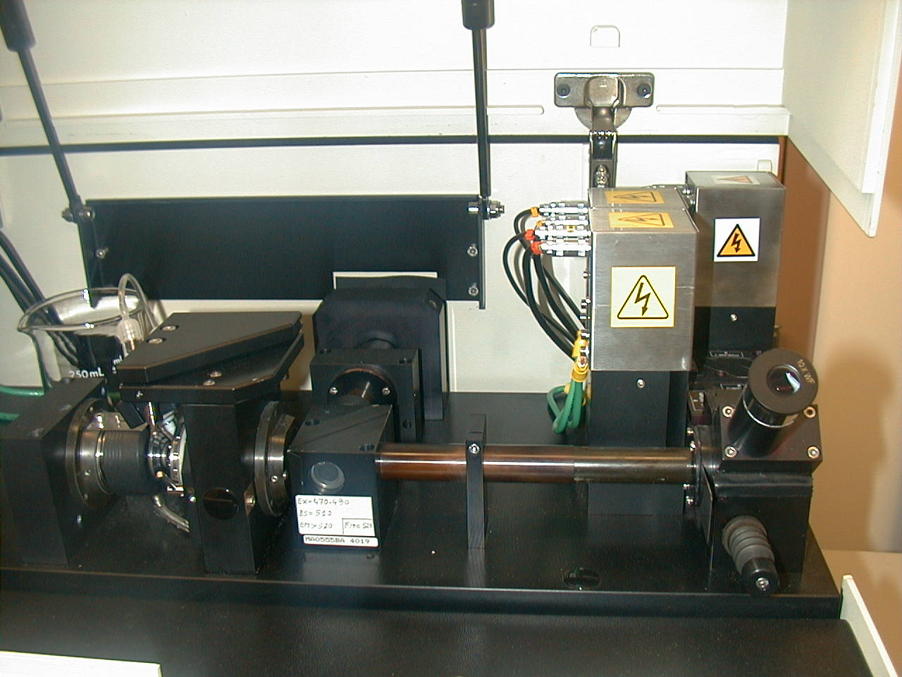
- Light must be converted from photons into volts to be measured
- We must select the correct detector system according to how many photons
we have available
- In general, we use photodiodes for forward scatter and absorption and PMTs for fluorescence and side
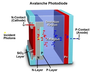
scatter
|
|
3
|
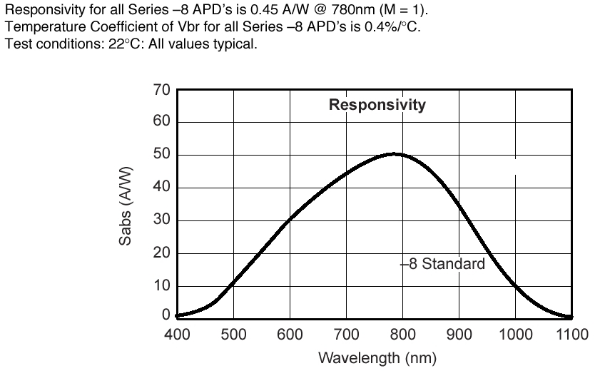
- A silicon photodiode produces current when photons impinge upon it
(example are solar cells)
- Does not require an external power source to operate
- Peak sensitivity is about 900 nm
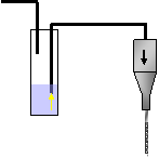
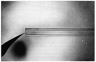
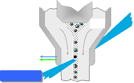
- At 900 nm the responsivity is about 0.5 amperes/watt, at 500 nm it is
0.28 A/W
- Are usually operated in the photovoltaic mode (no external voltage)
(alternative is photoconductive mode with a bias voltage)
- Have no gain so must have external amps
- quantum efficiency (f)%
= 100 x (electrons out/(photons in)
|
|
4
|
- Produce current at their anodes when photons impinge upon their
light-sensitive cathodes
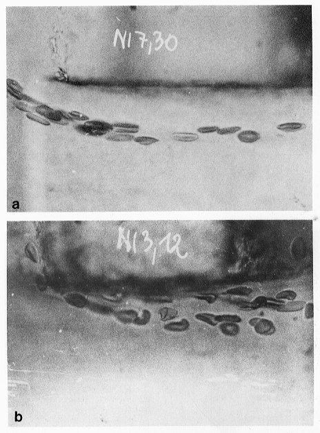
- Require external powersource
- Their gain is as high as 107 electrons out per photon in
- Noise can be generated from thermionic
emission of electrons - this is called “dark current”
- If very low levels of signal are available, PMTs are often cooled to
reduce heat effects
- Spectral response of PMTs is determined by the composition of the
photocathode
- Bi-alkali PMTs have peak sensitivity at 400 nm
- Multialkali PMTs extend to 750 nm
- Gallium Arsenide (GaAs) cathodes operate from 300-850 nm (very costly
and have lower gain)
|
|
5
|
|
|
6
|
|
|
7
|
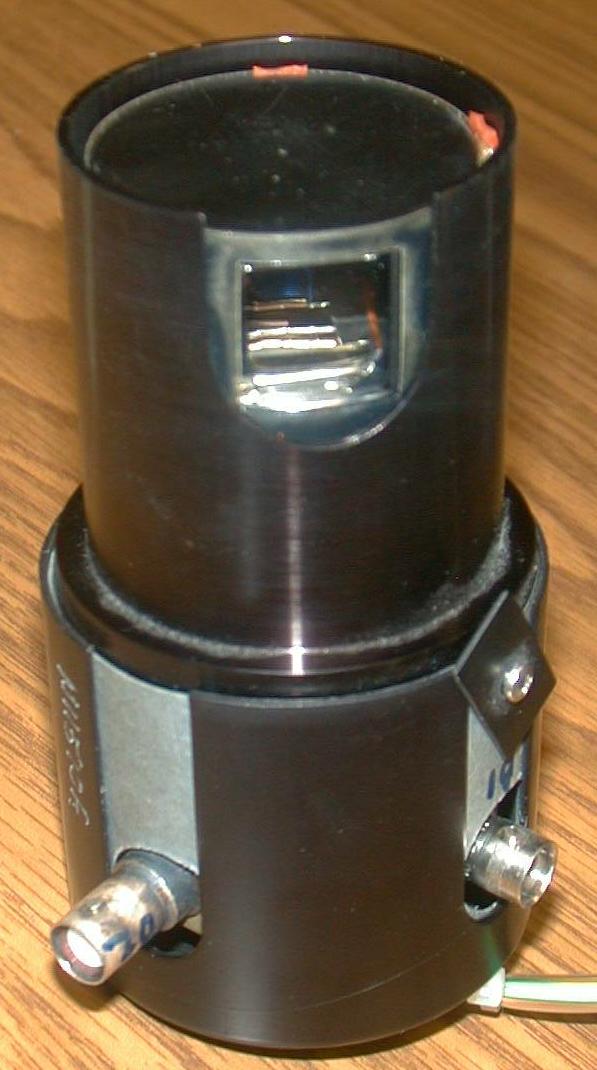
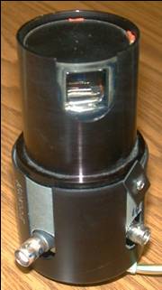
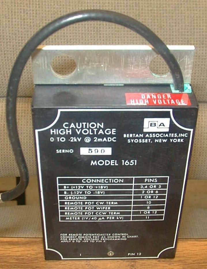
- High voltage regulation is critical because the relationship between the
high voltage and the PMT gain is
non-linear (almost logarithmic)
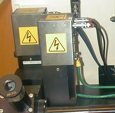
- PMTs must be shielded from stray light and magnetic fields
- Room light will destroy a PMT if connected to a power supply
- There are side-window and end-window PMTs
- While photodiodes are efficient, they produce too small a signal to be
useful for fluorescence
|
|
8
|
- Scatter detectors are frequently diode detectors
|
|
9
|
|
|
10
|
- The voltage on the PMT is applied to the dynodes
- This increases the “sensitivity” of the PMT
- A low signal will require higher voltages on the PMT to measure the
signal
- When the voltage is applied, the PMT is very sensitive and if exposed to
light will be destroyed
- Background noise on PMTs is termed “dark noise”
- PMTs generally have a voltage range from 1-2000 volts
- Changing the gain on a PMT should be linear over the gain range
- Changing the voltage on the PMT
is NOT a linear function of response
|
|
11
|
- Combines the best features of PMTs and photodiodes
- High quantum efficiency, good gain
- Gain is 102-103 (much less than PMTs)
- Problem with high dark current
|
|
12
|
- Charge Coupled devices (CCD) usually in our video cameras (also called
charged transfer devices)
- light causes accumulation of electric charge in individual elements
which release the charge at regular intervals
- Useful in imaging because they can integrate over time
- Not fast enough for flow cytometry application in general
|
|
13
|
- Photodiodes can operate in two modes - photovoltaic and photoconductive
- PMTs are usually used for fluorescence measurements
- Photodiodes are usually used for scatter
- PMTS are sensitive to different wavelengths according to the
construction of the photocathode
- PMTs are subject to dark current
- Voltages and gain are not linear
- Photodiodes are more sensitive than PMTs but because of their low gain,
they are not as useful for low level signals (too much noise)
|
|
14
|
|
|
15
|
|
|
16
|
|
|
17
|
|
|
18
|
|
|
19
|
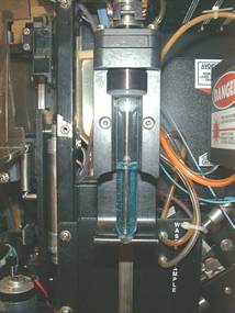
- Cells are always in suspension
- The usual fluid for cells is saline
- The sheath fluid can be saline or water
- The sheath must be saline for sorting
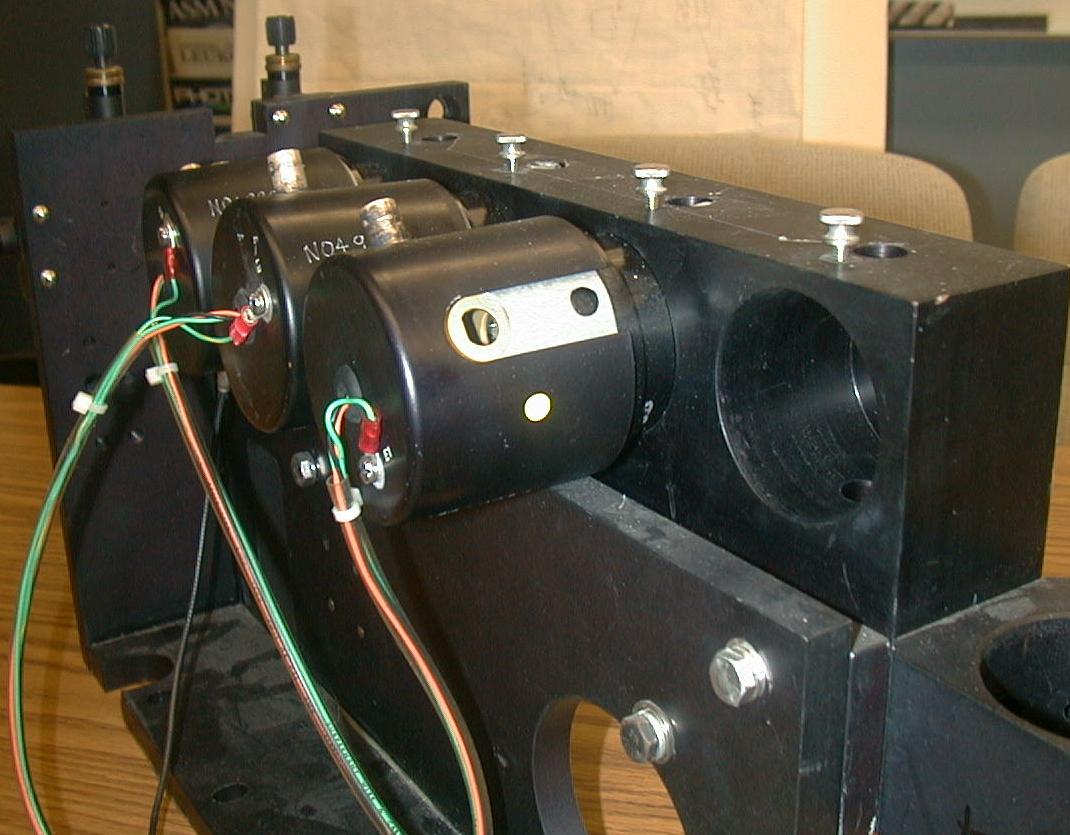
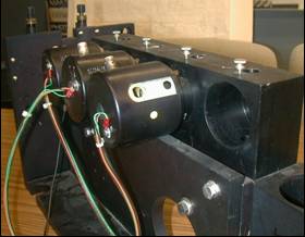
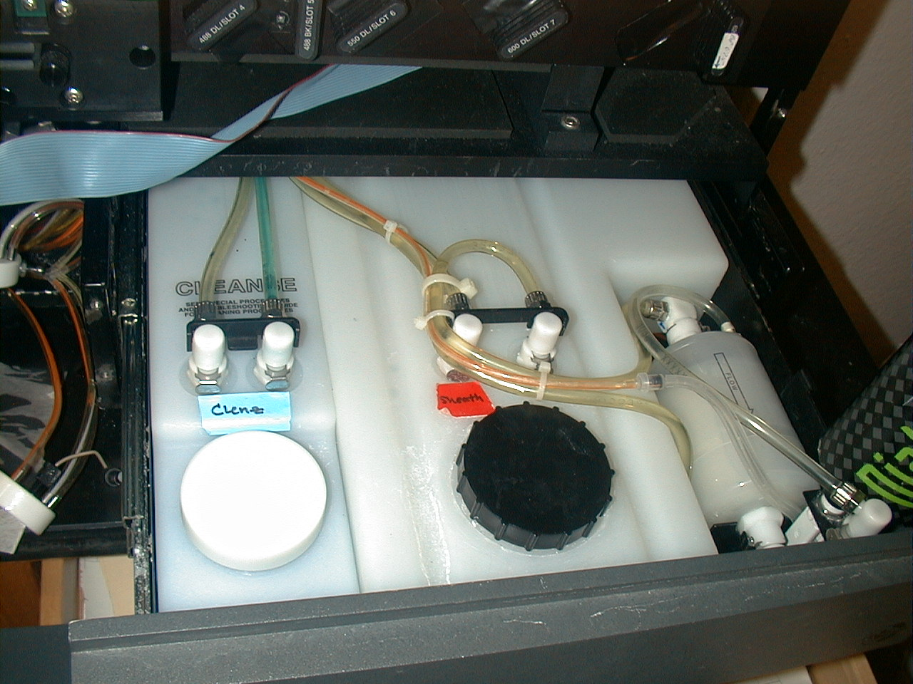
- Samples are driven either by syringes or by pressure systems
|
|
20
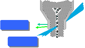
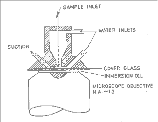
|
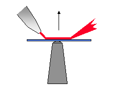
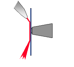
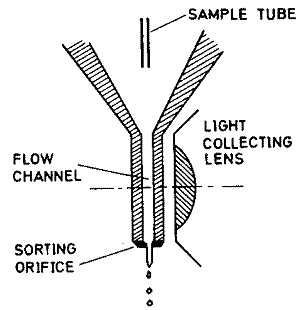
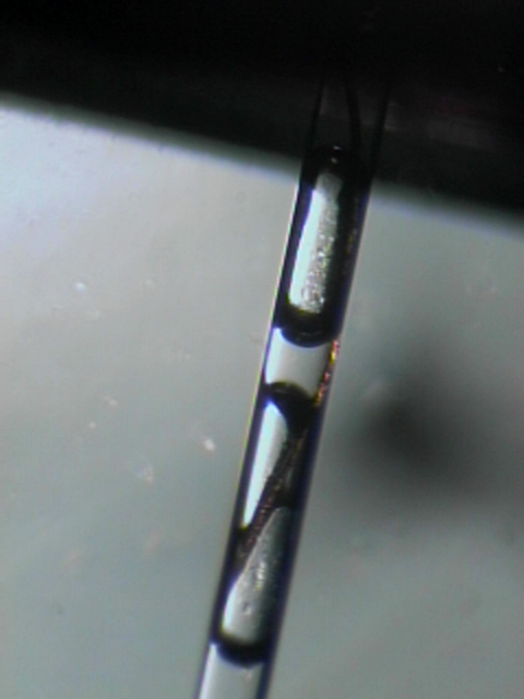
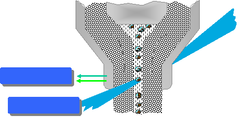
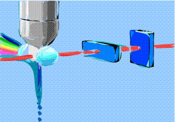
- Need to have cells in suspension flow in single file through an
illuminated volume
- In most instruments, accomplished by injecting sample into a sheath
fluid as it passes through a small (50-300 µm) orifice
|
|
21
|
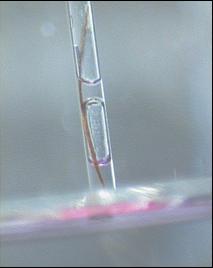
- When conditions are right, sample fluid flows in a central core that
does not mix with the sheath fluid
- This is termed Laminar flow
|
|
22
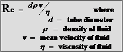
|
- Whether flow will be laminar can be determined from the Reynolds number
- When Re < 2300, flow is always laminar
- When Re > 2300, flow can be turbulent
|
|
23
|
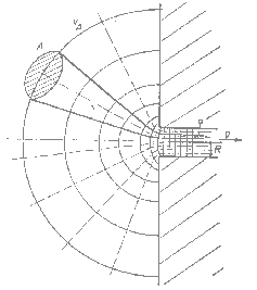
- The introduction of a large volume into a small volume in such a way
that it becomes “focused” along an axis is called Hydrodynamic Focusing
|
|
24
|
|
|
25
|
|
|
26
|
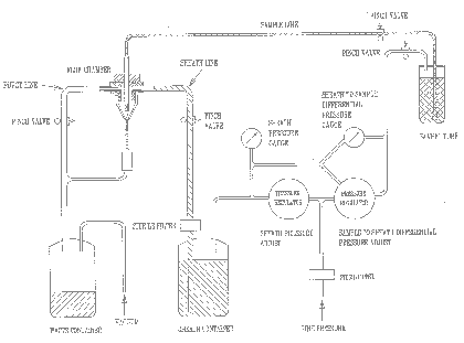
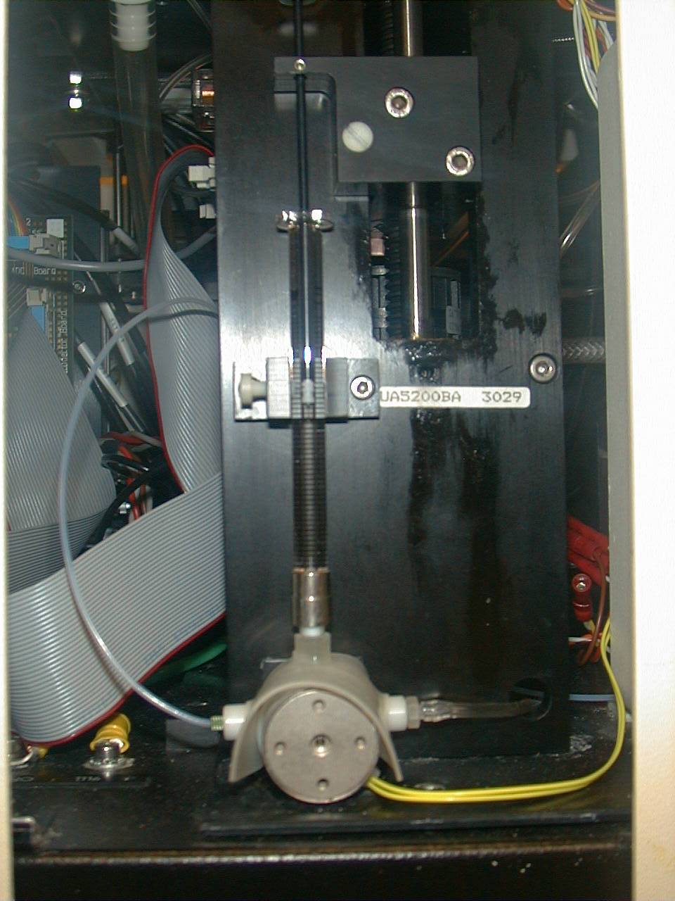
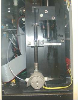
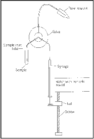
- How do we accomplish sample injection and regulate sample flow rate?
- Differential pressure
- Volumetric injection
|
|
27
|
- Use air (or other gas) to pressurize sample and sheath containers
- Use pressure regulators to control pressure on each container separately
|
|
28
|
- Sheath pressure will set the sheath volume flow rate (assuming sample
flow is negligible)
- Difference in pressure between sample and sheath will control sample volume
flow rate
- Control is not absolute - changes in friction cause changes in sample
volume flow rate
|
|
29
|
- Use air (or other gas) pressure to set sheath volume flow rate
- Use syringe pump (motor connected to piston of syringe) to inject sample
- Sample volume flow rate can be changed by changing speed of motor
- Control is absolute (under normal conditions)
|
|
30
|
|
|
31
|
|
|
32
|
|
|
33
|
- As cells (or other particles) are hydrodynamically focused, they
experience different shear stresses on different points on their
surfaces (an in different locations in the stream)
- These cause cells to orient with their long axis (if any) along the axis
of flow
|
|
34
|
- The shear stresses can also cause cells to deform (e.g., become more
cigar-shaped)
|
|
35
|
|
|
36
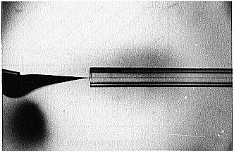
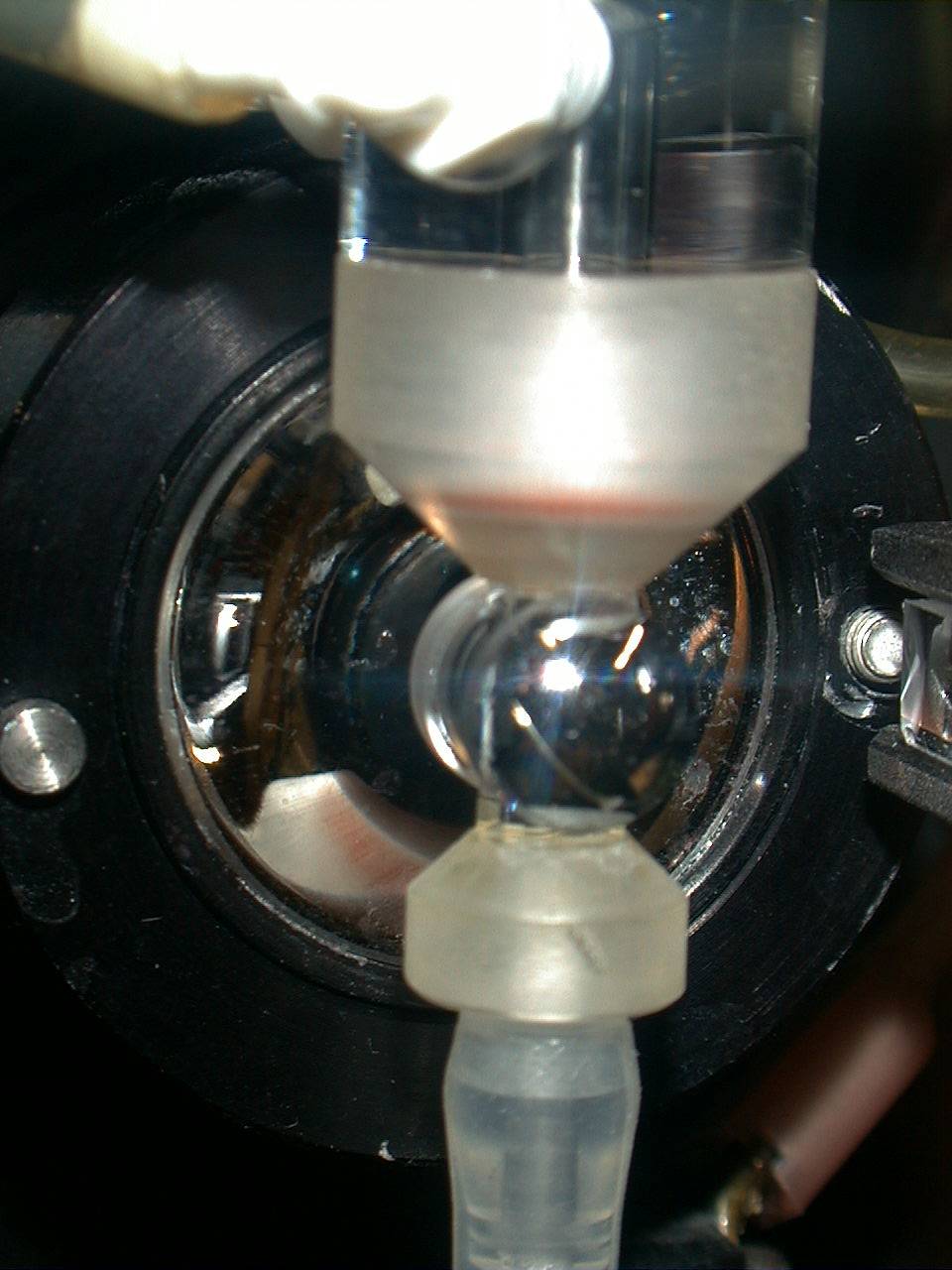
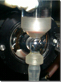
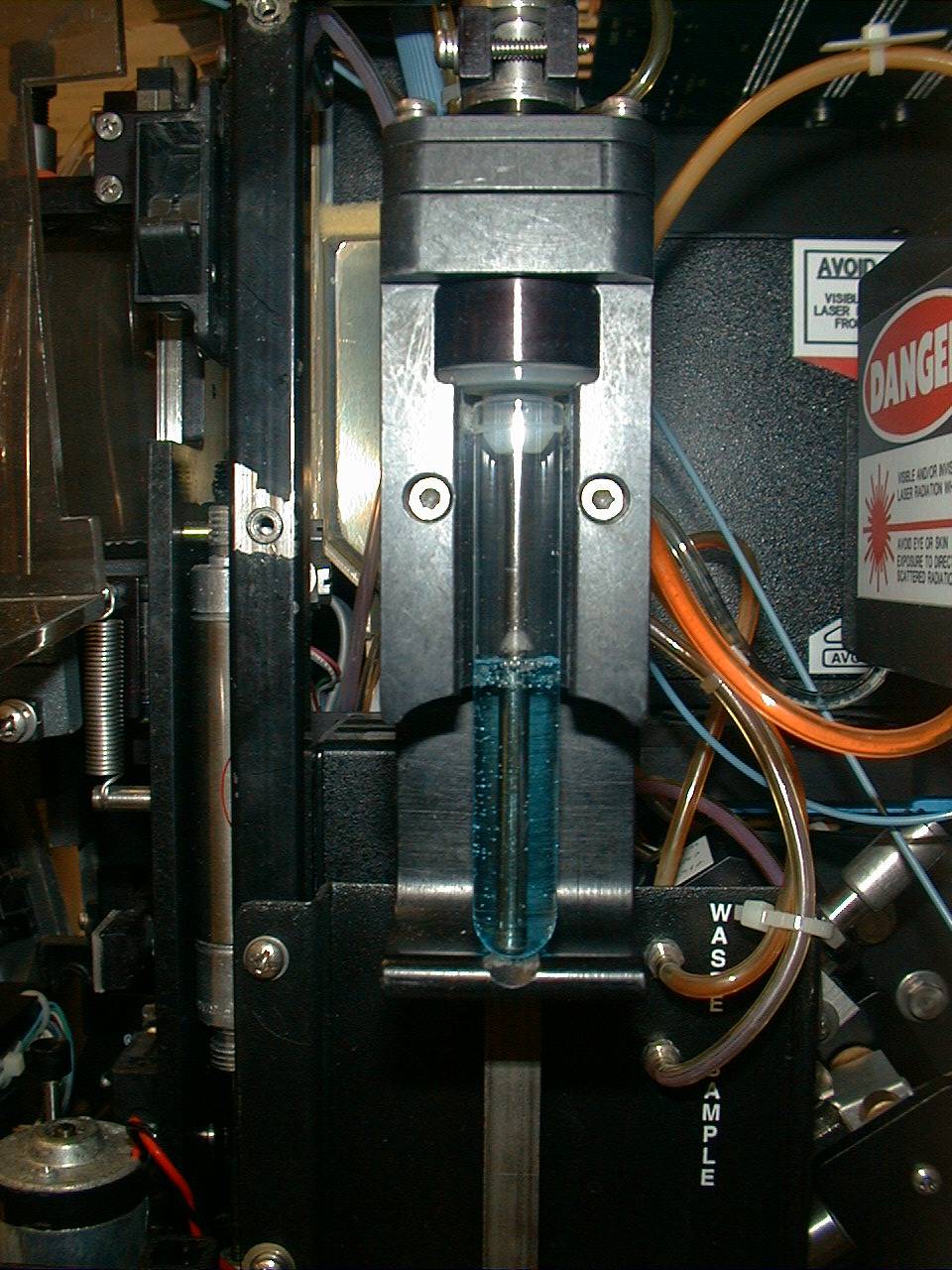
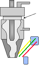
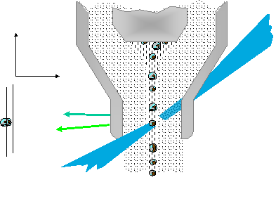
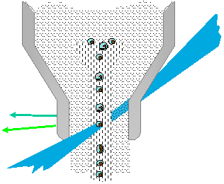
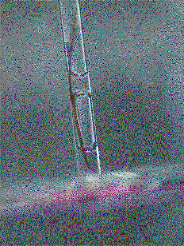
|
- The flow chamber
- defines the axis and dimensions of sheath and sample flow
- defines the point of optimal hydrodynamic focusing
- can also serve as the interrogation point (the illumination volume)
|
|
37
|
|
|
38
|
|
|
39
|
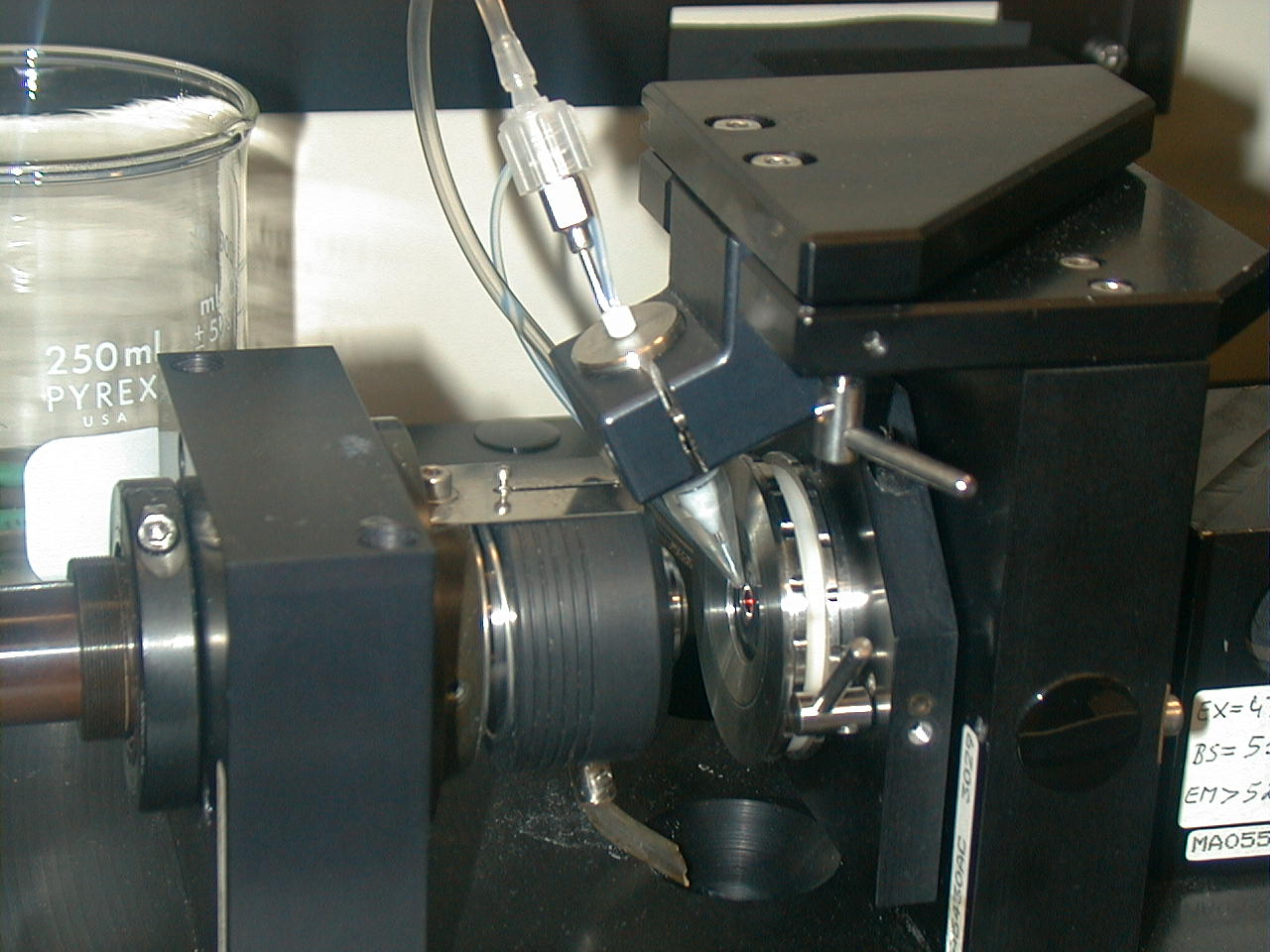
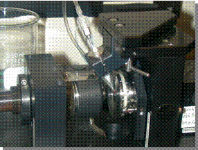
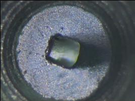
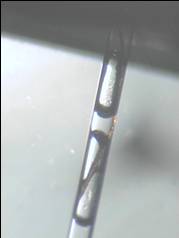
- Four basic flow chamber types
- Jet-in-air
- best for sorting, inferior optical properties
- Flow-through cuvette
- excellent optical properties, can be used for sorting
- Closed cross flow
- best optical properties, can’t sort
- Open flow across surface
- best optical properties, can’t sort
|
|
40
|
|
|
41
|
|
|
42
|
|
|
43
|
|
|
44
|
|
|
45
|
|
|
46
|
|
|
47
|
|
|
48
|
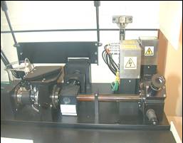
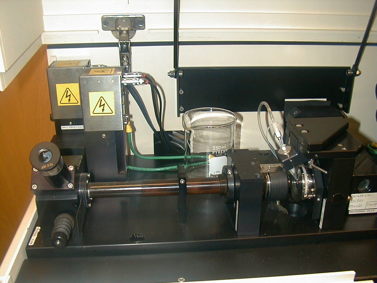
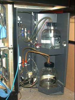
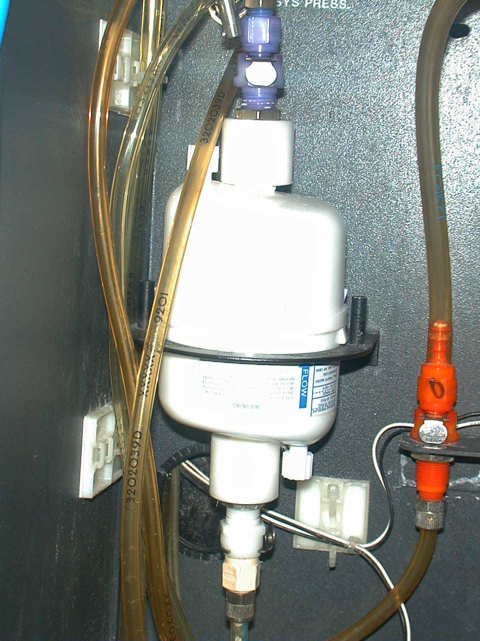
- Sample Collection and hydrodynamics
|
|
49
|
|
|
50
|
|
|
51
|
|
|
52
|
|
|
53
|
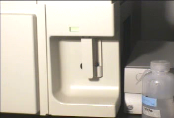
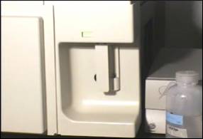
- Detection systems in flow cytometry
- Critical aspects of flow systems
- Flow must be laminar (appropriate Reynolds #)
- When Re < 2300, flow is always laminar
- Samples can be injected or flow via differential pressure
- There are many types of flow cells
- Blockages must be properly cleared to obtain high precision
- WEB http://www.cyto.purdue.edu
|

 Notes
Notes